
Company news
The features and operating procedures of distribution cabinets
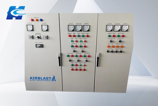
The product also adopts a large-screen LCD touch screen to conduct all-round monitoring of power quality such as voltage, current, frequency, useful power, useless power, energy and harmonics. Users can have a clear understanding of the operation status of the power distribution system in the computer room at a glance, which enables them to identify potential safety hazards early and avoid risks promptly.In addition, users can also choose functions such as ATS, EPO, lightning protection, isolation transformers, UPS maintenance switches, and mains power output branch circuits to ensure the safety and stability of the power distribution system in the computer room.
Operating Procedures
1. The distribution cabinet is the power distribution center of the ship, ensuring the normal operation of production and equipment. No irrelevant personnel are allowed to operate the switches on the board.
After the generator set is started, the speed-up switch on the power screen should be used to manually accelerate slowly until the generator enters the normal working state and the voltage and frequency reach the specified values. Only then can the switch be closed to supply power.
Iii. After the distribution board enters the distribution state, the speed-up switch of the power panel shall not be pulled at will, and the locking switch of the air circuit breaker shall not be used except in emergency situations.
Fourth, when generators are operated in parallel, they must be carried out strictly in accordance with the requirements and regulations of the paralleling conditions. Attention should be paid to phenomena such as reverse power (reverse flow) and paralleling failure.
V. When shutting down, the generator load should be cut off first, and then the machine should be stopped under no-load conditions. It is strictly prohibited to shut down the machine directly under load.
Vi. When switching shore power, all power switches on the shore power panel should be turned off first. Then, check the correctness of the wiring and phase sequence. Only after confirming that they are correct can the conversion from ship to shore power be carried out. It is strictly prohibited to operate under load.
Seven. Distribution cabinets should be regularly cleaned and maintained to ensure that the equipment is always in good working condition.
Viii. When the generator is in operation and the engine room personnel operate the distribution board, they should concentrate and operate carefully to prevent accidents. Otherwise, personal responsibility for the accident will be pursued.
Ix. The charge and discharge board is the emergency distribution board of the ship. The on-duty engine engineer should frequently check its working condition, ensure sufficient low-voltage power at all times, and monitor the working status of the magnetic saturation voltage stabilizer through the instruments on the board.
X. During normal navigation, all switches on the distribution board should be turned on to ensure that the generator can be started at any time and the emergency lighting can be put into use immediately.
Eleventh, it is hoped that all members of the rotation department will strictly abide by the above points.
First, according to the schematic diagram, terminals should be connected for those not in the same position. Never connect three wires to one terminal. When checking for errors, it's not like that. You can only check them one by one according to the schematic diagram.
1. Selection of the cross-section of the conductor
The wires for the mains power (AC 220V) voltage circuit should be 1.5 square millimeters. The current circuit uses 2.5 square millimeters. A battery of 1.5 square millimeters is generally sufficient.
When wiring, make sure that the signals at both ends of the wires correspond to avoid unnecessary errors.
The most important thing is to understand the schematic diagram and wiring diagram clearly.
Second, if you are a beginner, you should first review the drawings, organize your own train of thought, and also check if there are any problems with the drawings. If there are any parts you don't understand, you can figure them out first. This is beneficial for making lines. Then the wiring began. The entire wiring process requires meticulousness. Of course, if you are an experienced hand, there is no need to say so much.
Construction personnel should carefully read and be familiar with the secondary line symbols. They should check the secondary wiring diagram against the schematic diagram to ensure that the wiring diagram is correct and error-free.
Requirements for secondary wiring construction: Construct according to the drawing and ensure correct wiring. The wires and electrical components should be firmly and reliably connected by bolts, plugs, welding or crimping, etc., and the wiring should be good. The wiring is neat, clear and beautiful. The wire insulation is good and there is no damage. There should be no joints in the wires inside the cabinet. The circuit number is correct and the handwriting is clear.
The selection of the cross-sectional area of the cable core wire should also meet the following requirements:
(1) Current circuit: The working accuracy grade of the current transformer should be ensured. At this time, if there is no reliable basis, the maximum short-circuit current can be determined according to the current capacity of the circuit breaker.
(2) Voltage circuit: When all protection devices and safety automatic devices are in operation (considering development, when the load of the voltage transformer is at its maximum), the cable voltage drop from the voltage transformer to the protection and automatic device screen should not exceed 3% of the rated voltage.
(3) Operating circuit: Under the maximum load, the voltage drop from the operating busbar to the equipment should not exceed 10% of the rated voltage.
Iii. The secondary winding of the current transformer must not be open-circuited. The secondary side of the voltage transformer must not be short-circuited
Before the secondary wiring, you should familiarize yourself with the drawing
Schematic diagram. It indicates the working principles and interactions of each circuit. The drawing soon shows the connection methods of each component in the secondary circuit and also indicates the connections related to the primary circuit.
2. Expansion diagram
3. Terminal block diagram
4. Install the wiring diagram
CATEGORIES
LATEST NEWS
CONTACT US
Name:
Mobile:13861751023
Tel:86-0510-81020919
Email:rdh518@huikongkeji.com
Add:No. 217, Xitai Road, Meicun Industrial Park, New District, Wuxi City, Jiangsu Province